EWP Hangers
Fire Wall Hangers
FWH
Reference Series: DGHF
2015, 2018 & 2021 IBC/IRC Code Compliant
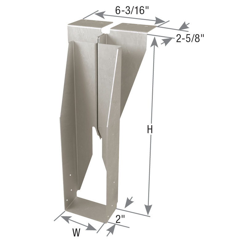
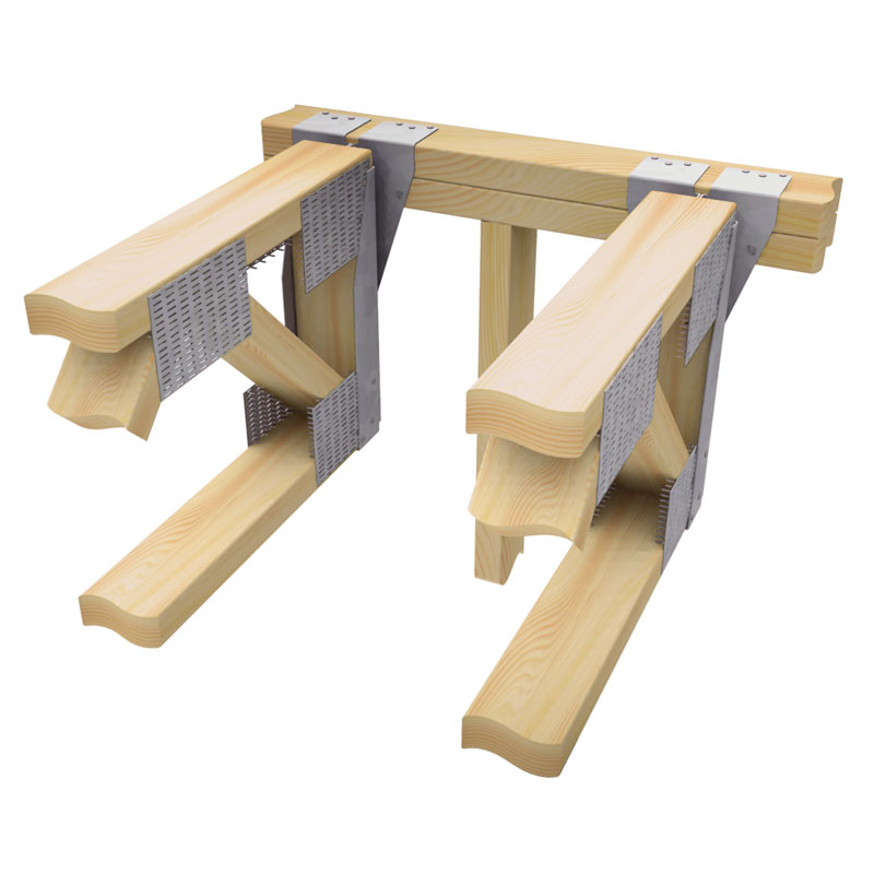
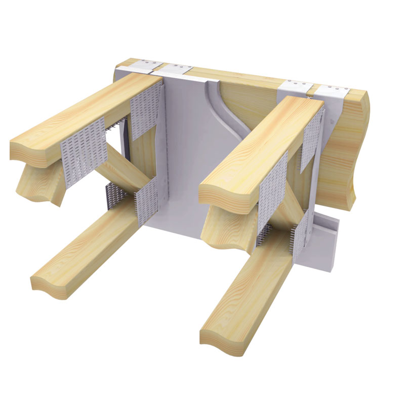
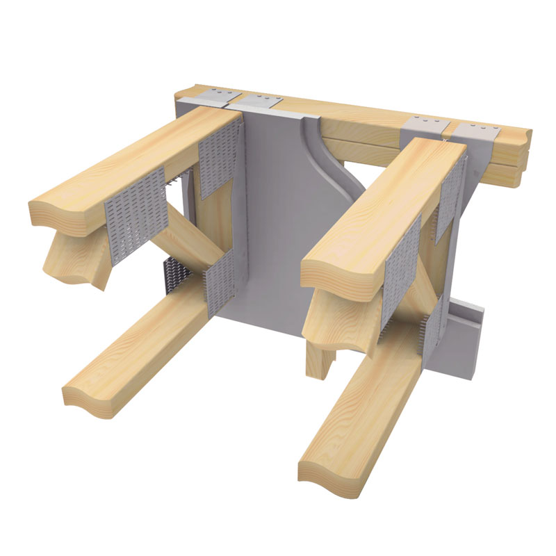
The FWH Fire Wall Hanger is designed for attaching truss, I-joist, solid sawn lumber, or engineered wood floor framing members to double wall top plates or minimum 2-ply 2x solid sawn header fire rated wood frame walls. The advanced design allows the installation of the FWH before the 5/8" gypsum wallboard (drywall) is attached and permits the building project to be completely framed-up, and weather-tight before the gypsum wallboard sheathing work starts.
2 Hour Fire Rating: FWH hangers are tested per ASTM E814 standards. When installed on one side of a maximum 2 hour fire-rated wall assembly, the penetration of the MiTek FWH Fire Wall Hanger through the gypsum wallboard will not reduce the fire resistive rating of the 2 hour fire resistive assembly.
Patents: U.S. No. 11,649,626
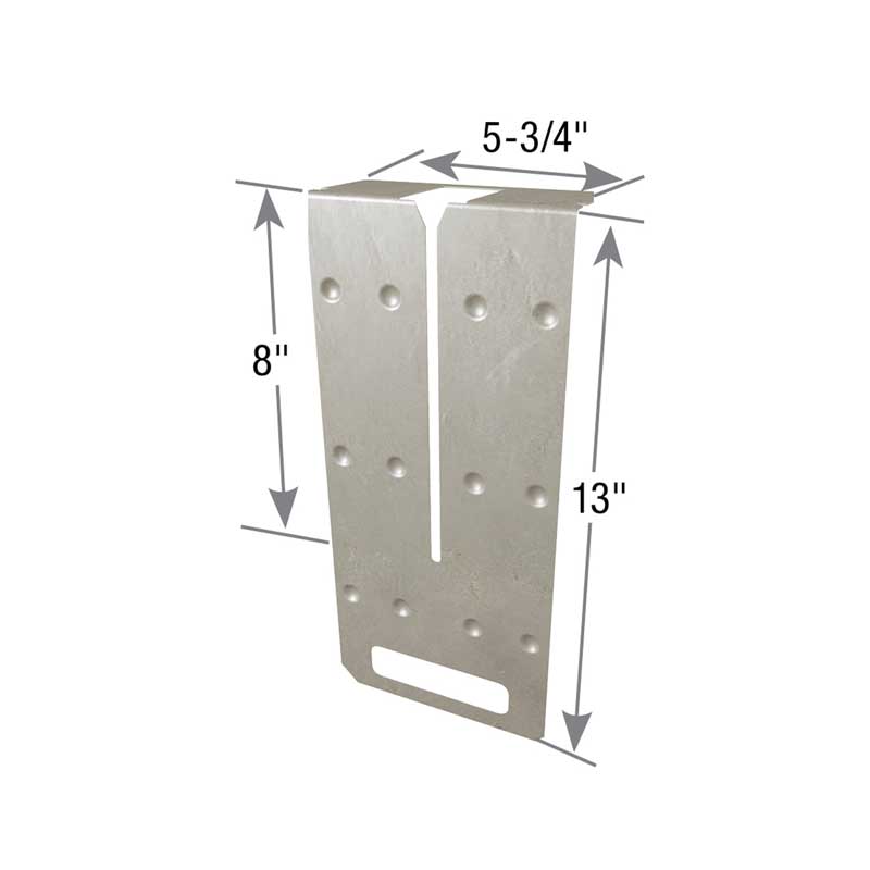
Materials: 14 gauge
Finish: G90 galvanizing
Code Reports:
View Code Report Table
Resources
Installation
- Install the face of hanger flanges tight to stud wall framing.
- For wall framing, hangers do NOT need to be installed at stud locations for full design values.
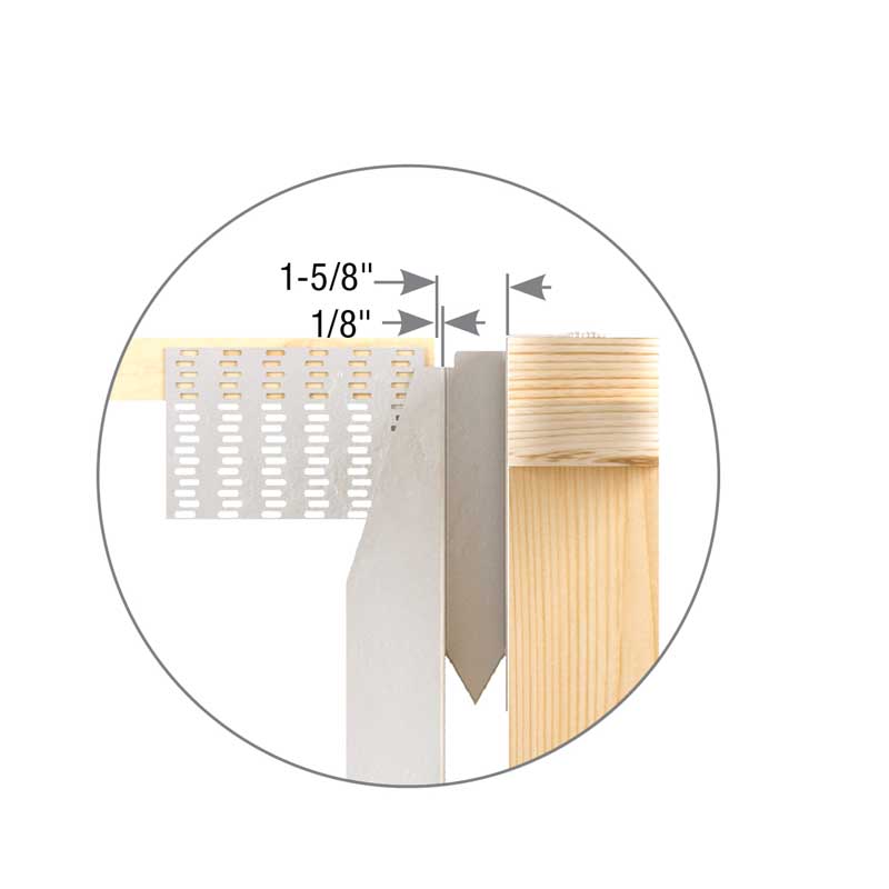
- The end of the truss/joist should measure 1-5/8″ from the face of the supporting wall. See Figure 1.
- The truss/joist should bear fully on the FWH seat with a gap no greater than 1/8” between the end of the supported member and the hanger. See Figure 1.
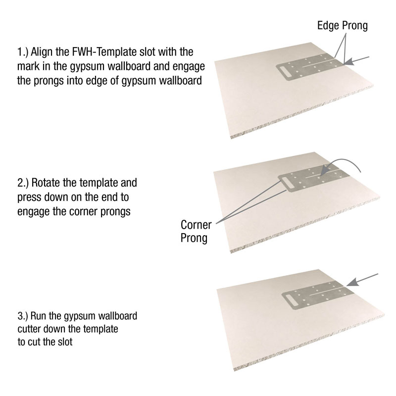
- Gypsum Wallboard Installation – Use the FWH-T template to slot cut the gypsum wallboard. See FWH-T Template Sequence image. Slide the gypsum wallboard into position and fasten to the framing members meeting minimum requirements specified by code.
Need Help or Have a Question? Contact Customer Service or Call 800-328-5934
FWH Fire Wall Hanger
FWH Installation Instructions
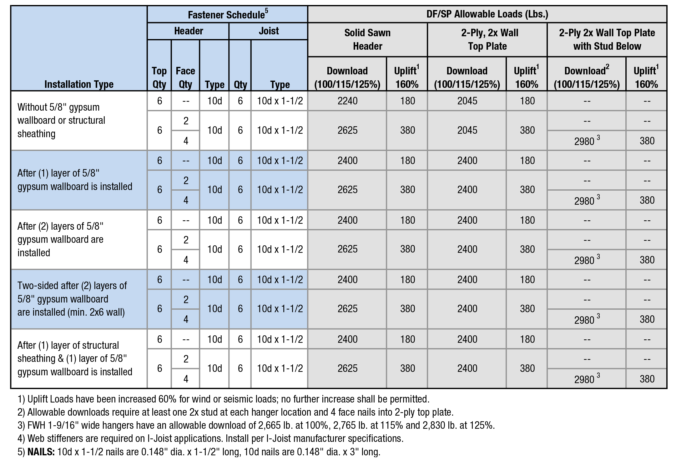
Load Tables
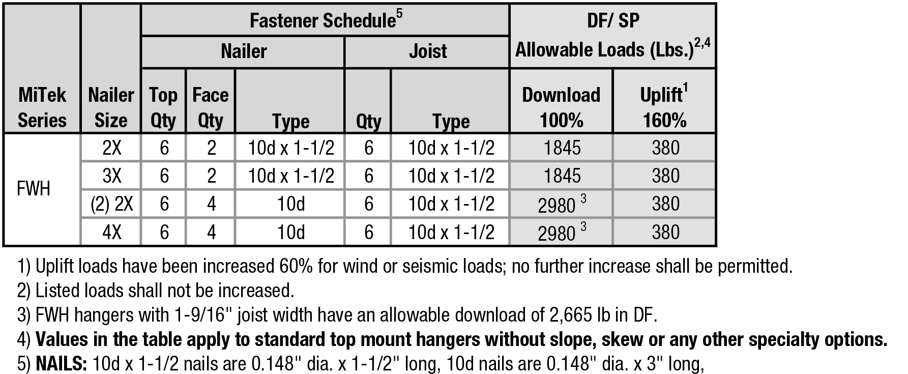
Fastener / Allowable Load Table
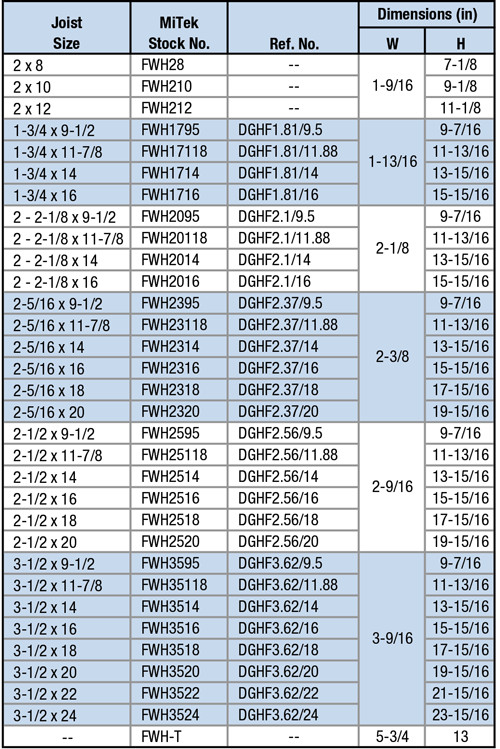
Product / Geometry Table
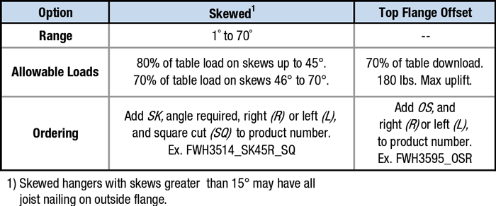
Option Details:
Code Report Table
FWH-T
3-View Product Drawings
| MiTek Stock # | Download or View Files | |||
|---|---|---|---|---|
| FWH17118 | DWG | DXF | View Image | |
| FWH1714 | DWG | DXF | View Image | |
| FWH1716 | DWG | DXF | View Image | |
| FWH1795 | DWG | DXF | View Image | |
| FWH20118 | DWG | DXF | View Image | |
| FWH2014 | DWG | DXF | View Image | |
| FWH2016 | DWG | DXF | View Image | |
| FWH2095 | DWG | DXF | View Image | |
| FWH210 | DWG | DXF | View Image | |
| FWH212 | DWG | DXF | View Image | |
| FWH23118 | DWG | DXF | View Image | |
| FWH2314 | DWG | DXF | View Image | |
| FWH2316 | DWG | DXF | View Image | |
| FWH2318 | DWG | DXF | View Image | |
| FWH2320 | DWG | DXF | View Image | |
| FWH2395 | DWG | DXF | View Image | |
| FWH25118 | DWG | DXF | View Image | |
| FWH2514 | DWG | DXF | View Image | |
| FWH2516 | DWG | DXF | View Image | |
| FWH2518 | DWG | DXF | View Image | |
| FWH2520 | DWG | DXF | View Image | |
| FWH2595 | DWG | DXF | View Image | |
| FWH28 | DWG | DXF | View Image | |
| FWH35118 | DWG | DXF | View Image | |
| FWH3514 | DWG | DXF | View Image | |
| FWH3516 | DWG | DXF | View Image | |
| FWH3518 | DWG | DXF | View Image | |
| FWH3520 | DWG | DXF | View Image | |
| FWH3522 | DWG | DXF | View Image | |
| FWH3524 | DWG | DXF | View Image | |
| FWH3595 | DWG | DXF | View Image | |
Non-Structural: Product is not load rated and does not require code evaluation.