Concrete and Masonry
Foundation Straps
LSTAD / STAD
Reference Series: LSTHD, STHD
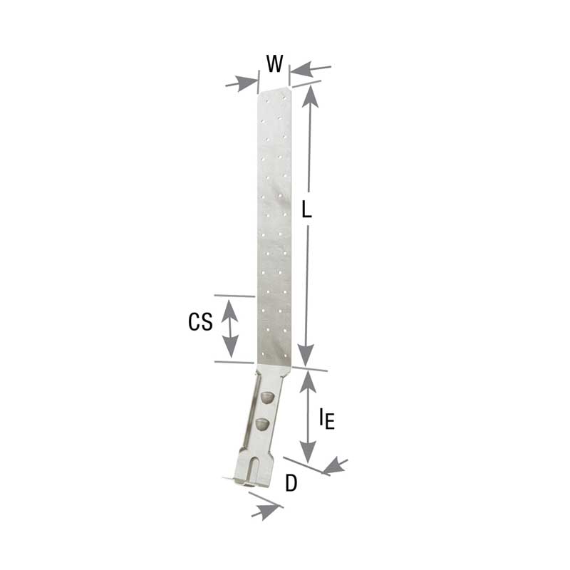
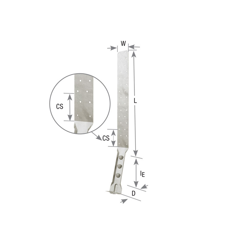
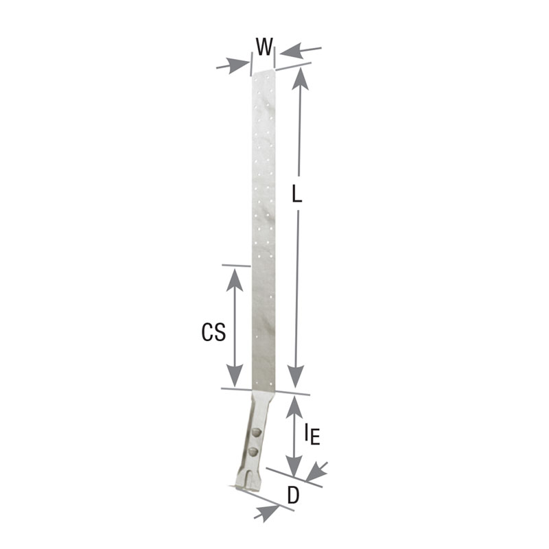
The coined dimples below the embedment line allow for increased concrete bonding. These holdowns retain high uplift capacity even when installed at corners of foundation stemwalls. Ideal for use with built up 2x end posts.
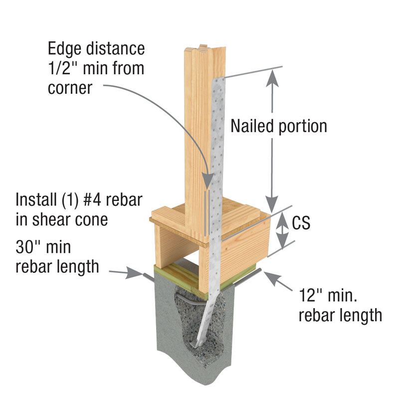
RJ after the model indicates LSTAD or STAD for rim joist applications as in STAD8RJ. Rim joist models provide for a 17" clear span without the loss of strap nailing.
RJ after the model indicates LSTAD or STAD for rim joist applications as in STAD8RJ. Rim joist models provide for a 17" clear span without the loss of strap nailing.
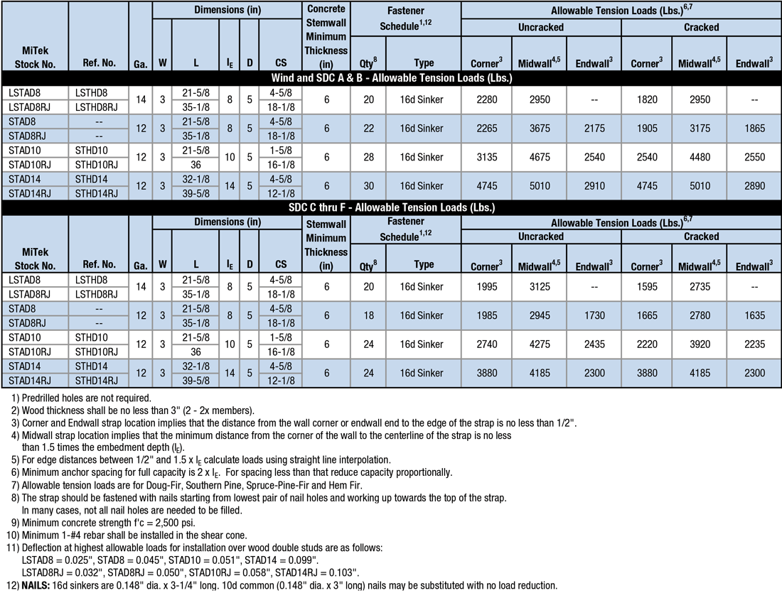
Materials: LSTAD – 14 gauge; STAD – 12 gauge
Finish: G90 galvanizing
Code Reports:
View Code Report Table
Installation
- Use all specified fasteners. The bottom (2) nails are for form board attachment only and do not contribute to fastener schedule requirements.
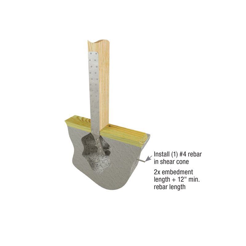
- Embed holdown in concrete to the embedment line (bend line).
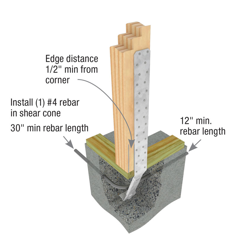
- See illustrations for requirements on rebar, edge distances, and clear spans.
- Bending the strap horizontally 90° to facilitate wall placement may cause concrete behind the embedded strap to break away at the top edge (spalling). If the spall is 1″ or less from the top edge of the concrete, no load reduction is necessary. If the spall is between 1″ and 4″ the allowable load is 0.90 of the published load table load.
- When installing on lumber less than 3-1/2″ wide, wood splitting may occur. To reduce splitting, use 10d (0.148″) x 1-1/2″ nails or fill every other hole with 16d (0.162″ x 3-1/2″) common nails. Reduce allowable loads per code requirements accordingly.
- These straps do not secure concrete sections together at cold joints; take other measures to transfer the load. If there is a cold joint between slab and foundation, the minimum embedment must be made into the foundation. Fastening opportunities may be reduced because the slab pour level may be higher than some nail holes. Using fewer fasteners will reduce allowable loads. Reduce allowable load by the code capacity for each fastener not installed.
- To achieve full table loads the minimum center-to-center spacing is twice the embedment depth (IE) when resisting tension loads at the same time.
- Where fewer fasteners are used in the structural wood member, reduce loads according to the code.
- There may be an increase in the amount of deflection if the strap is installed on the outside of the sheathing, versus directly to the framing members.
- Strap may be bent one complete cycle to aid installation.
- For installation in severe corrosion environments, see Corrosion Information Click here.
Need Help or Have a Question? Contact Customer Service or Call 800-328-5934
LSTAD Foundation Strap
Code Report Table
3-View Product Drawings
| MiTek Stock # | Download or View Files | |||
|---|---|---|---|---|
| STAD10 | DWG | DXF | View Image | |
| STAD10RJ | DWG | DXF | View Image | |
| STAD14 | DWG | DXF | View Image | |
| STAD14RJ | DWG | DXF | View Image | |
| STAD8 | DWG | DXF | View Image | |
| STAD8RJ | DWG | DXF | View Image | |