
ICC CODE COUNTS ARTICLE
ICC CODE COUNTS ARTICLE: OCTOBER 2017
ASD VS. LRFD DESIGN
Every building today is designed using one of two different methodologies in the International Building Code (IBC): allowable stress design (ASD) or load and resistance factor design (LRFD). How well do you actually understand these two methodologies and how they differ?
To answer that question, let’s look at the fundamental concepts behind both.
ASD
Allowable Stress Design, or Allowable Strength Design, uses the following design methodology:
Required Strength ≤ Allowable Strength
or
Required Strength ≤ Available Strength
On the left hand, the required strength is the applied load, as determined by the relevant building code or referenced standard (typically ASCE/SEI 7). This represents the actual loads expected to be applied to the structure. On the right hand is the available (allowable) strength, which reflects a force that keeps the material stress below some predefined maximum allowable stress. This allowable strength is the calculated nominal strength divided by a factor of safety. The nominal strength represents the actual strength based on engineering principles and is determined by the appropriate design specification for that material (steel, concrete, wood, etc.).
In equation form, borrowing steel design terminology, this is expressed as:

Of course, buildings have complicated dynamic loads and must be designed for load combinations that act simultaneously. Section 1602.1 of the 2015 IBC lists all of these loads, but the most common are:
D = Dead Load (material weight – static)
L = Live Load (floor occupancy)
Lr = Roof Live Load
S = Snow Load
W = Wind
E = Earthquake
How should the probability of any of these loads acting simultaneously be determined? For ASD, the 2015 IBC provides combinations and accounts for the probability of simultaneous combinations by reducing some of their magnitudes. All of these combinations are given in Section 1605.3, but the most common are:
D
D + L
D + (Lr or S)
D + 0.75 L + 0.75(Lr or S)
D + (0.6 W or 0.7 E)
D + 0.75(0.6 W) + 0.75 L + 0.75(Lr or S)
D + 0.75(0.7 E) + 0.75 L + 0.75 S
0.6 D + 0.6 W
Notice these loads are not factored (increased): they represent actual expected service loads. The engineer must check all applicable combinations to determine the combination that creates the highest stress.
Also note that some of the loads are reduced when grouped with dynamic loads (wind, snow, roof live, earthquake). These reductions represent a rational method to balance the probability of nature with economics and safety.
With ASD, the factor of safety is not connected to the load combinations. Since it is on the resistance side of the equation, it varies only with the type of force (axial, shear, bending moment). Its role is to reduce the nominal strength to a level below some predefined allowable value and to be on a level that is comparable (≥) to the expected applied loads.
LRFD
Load and Resistance Factor Design, also often called Strength Design, starts with the same basic design methodology as ASD:
Required Strength ≤ Available Strength
In equation form, again borrowing terminology from steel design, it is expressed as:

Comparing the two equations, we see that there is not an apparent factor of safety term as there is with ASD.
Again, the nominal strength is reduced, but it is reduced by a resistance factor Φ that is configured for a specific material type (steel, wood concrete, etc.) under a specific load type (bending, tension, compression, etc.) and often for a specific type of failure mode or limit state (ductile, brittle, concrete break out, epoxy bond failure, etc.).
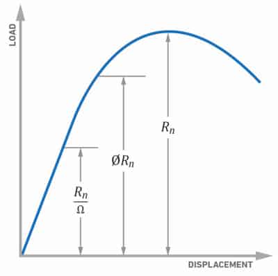
The resistance factor may also account for known variations in design assumptions and fabrication or installation factors known to have a potential negative impact on the available strength. The available strength in LRFD (ΦRn) is still significantly higher than the available strength in ASD (Rn/Ω).
The second major difference with LRFD is that the required strength on the left side is determined by increasing the applied loads based on how they are combined. All of these load factors are given in Section 1605.2 of the 2015 IBC, but the most common are:
1.4 D
1.2 D + 1.6 L + 0.5(Lr or S)
1.2 D + 1.6(Lr or S) + (ƒ1 L or 0.5 W)
1.2 D + 1.0 W + ƒ1 L + 0.5(Lr or S)
1.2 D + 1.0 E + ƒ1 L + ƒ2 S
0.9 D + 1.0 W
0.9 D + 1.0 E
Where f1 and f2 are conditional adjustment factors
This increase is quite different from what we saw in ASD, so what’s going on here?
The increase in loads with LRFD serves two purposes. First, they increase the expected applied loads and their effects to a level that more closely balances the LRFD available strength. Second, the increase more directly acknowledges uncertainty about dynamic, time-varying transient loads like wind, snow and earthquake and uses individual load factors to increase them when combined with other loads.
The load factors also reflect the possibility of “overload” as well as the probability that maximum transient peaks may be different (i.e., higher) when they act in combination with other loads. Look closely and you’ll see that a few factors change for the same load depending on the combination.
COMPARING ASD TO LRFD
The graph below illustrates the difference between the ASD and LRFD available strength values (right-hand side of the equation) when using a simplified load-deflection graph for steel (but the concepts apply to other materials too). LRFD has higher available strength when directly compared to the ASD available strength.

However, LRFD uses load factors so it also has a higher “required strength” on the left-hand side of the equation. Both methods can be used to keep material stresses within the elastic range but they are different design methodologies and it is incorrect to say one is better than the other.
If the LRFD equation is thought of as:

We can, more or less, see a factor of safety emerging with LRFD. In this regard, LRFD arguably applies a more rational approach by spreading out the safety factor to both sides of the equation, accounting for uncertainty in loads (U) as well as uncertainty in material strength/construction methods (Φ). Therefore, LRFD appears to be better equipped to deal with uncertainty because its “safety factor” is dynamic.
Comparing both on the same building design, the general consensus is that LRFD will result in stronger structures for more highly dynamic loads and ASD will result in stronger structures for less variable (more predicable) loads. However, in many cases the differences are not significant: both methods have been used successfully for decades and are acceptable under the 2015 IBC.
{Disclosure statement}
The views and opinions expressed in this article are those of MiTek USA, Inc. and do not necessarily reflect those of the International Code Council, or Hanley Wood.