Plated Truss
Truss Brace and Spacer
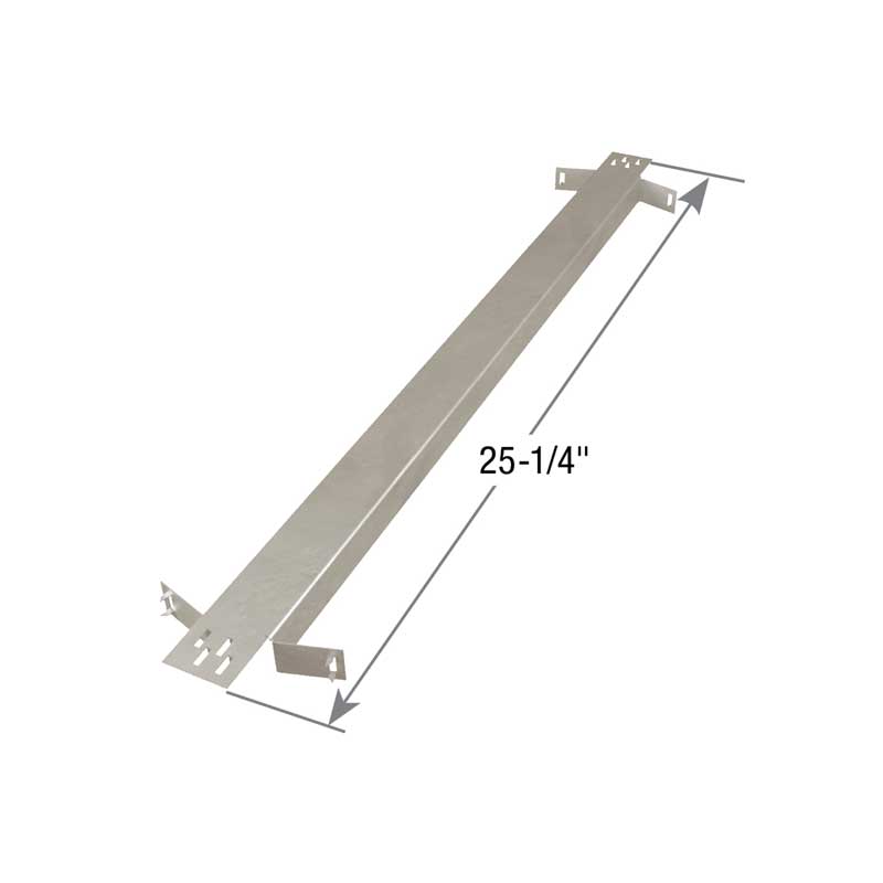
Stabilizer
Reference Series: TSBR
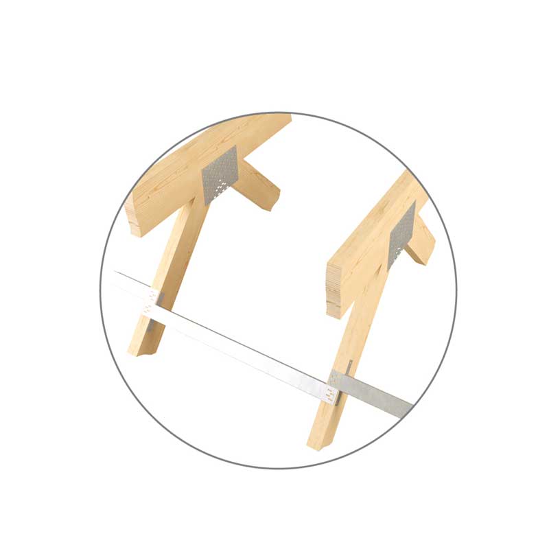
The Stabilizer™ Truss Brace and Spacer provides temporary construction bracing in the roof and ceiling planes, as well as permanent lateral bracing for webs as specified by your truss engineering.
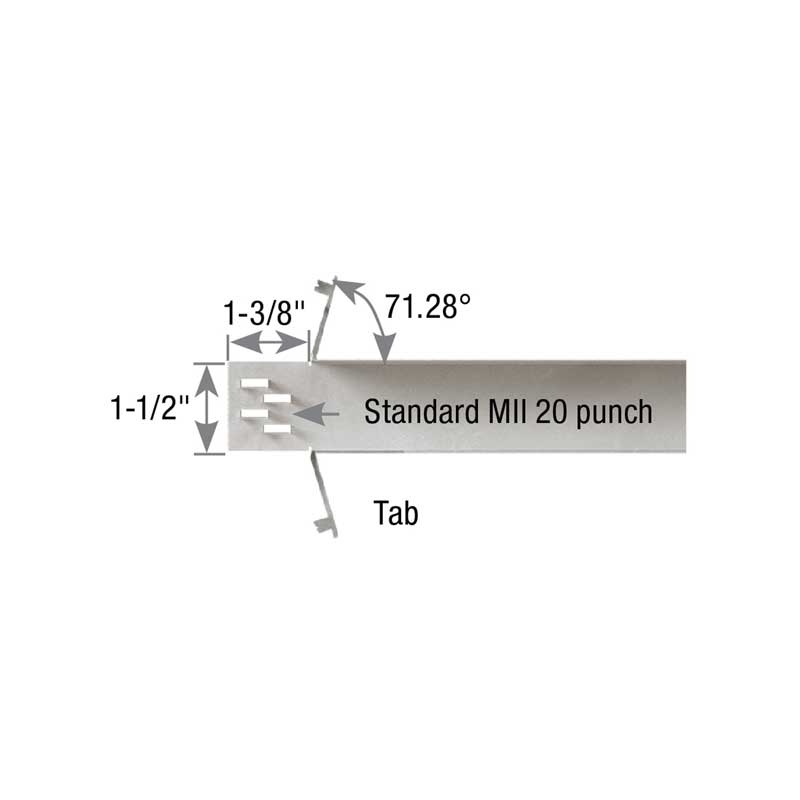
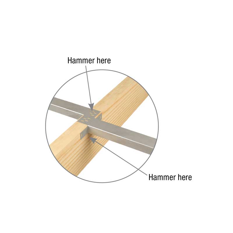
The Stabilizer™ is easily installed by embedding the patented MII 20 teeth on the top flange straight into the edge of the truss member to be braced with a framing hammer. The side tabs are then secured by driving the teeth into the face of the truss member being braced.
The Stabilizer™ is easily installed by embedding the patented MII 20 teeth on the top flange straight into the edge of the truss member to be braced with a framing hammer. The side tabs are then secured by driving the teeth into the face of the truss member being braced.
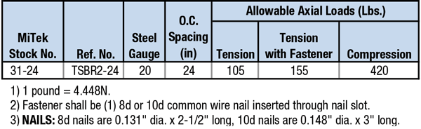
Materials: 20 gauge
Finish: G90 galvanizing
Code Reports:
View Code Report Table
Installation
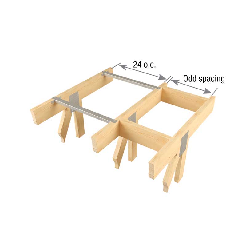
- Use 31-24 for standard 24″ o.c. spacing. For odd spacing, cut and insert a solid block between the trusses.
- Typically, The Stabilizer™ is installed at 6’– 8′ centers along the roof plane and 10’– 15′ along the ceiling plane. (Refer to engineering specifications BCSI 1-03, published by The Truss Plate Institute for specific bracing requirements.)
- The Stabilizer™ must be supplemented with diagonal bracing in the roof and ceiling planes and cross bracing in the web plane at required intervals.
- Web forces are not to exceed 8000 lbs.
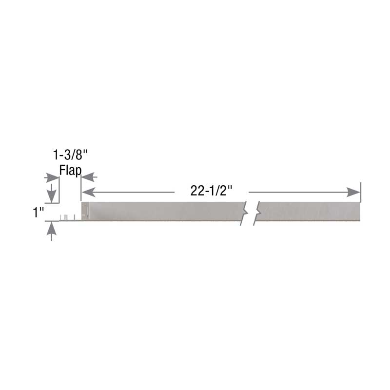
- The Stabilizer™ is properly installed when the top flap and side tabs are flush with the member being braced.
- Important: The erection contractor is responsible for determining and installing the temporary bracing for the structure, including the trusses. It is most important for the installer to provide adequate means for bracing the first truss installed. The performance of the entire bracing system depends on the adequacy of the ground bracing or other means of bracing the first group of trusses installed. The building designer is responsible for the permanent bracing design of the overall structure including the truss. This includes the design of required supplemental diagonal and cross bracing.
Need Help or Have a Question? Contact Customer Service or Call 800-328-5934
31-24 Stabilizer™