Plated Truss
Valley Truss Tie
VTT
Reference Series: VTCR
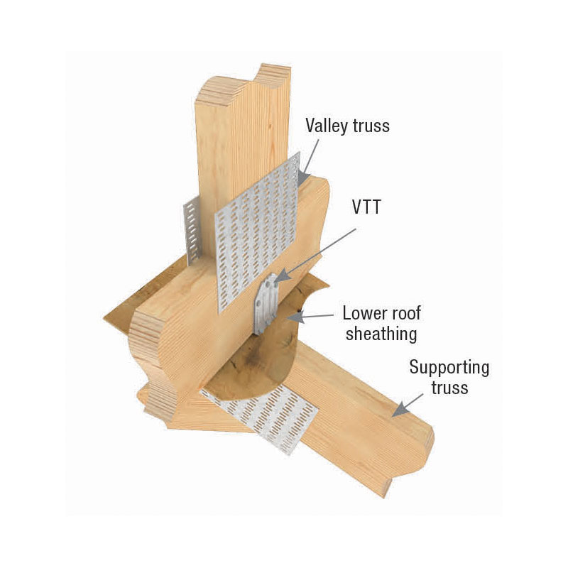
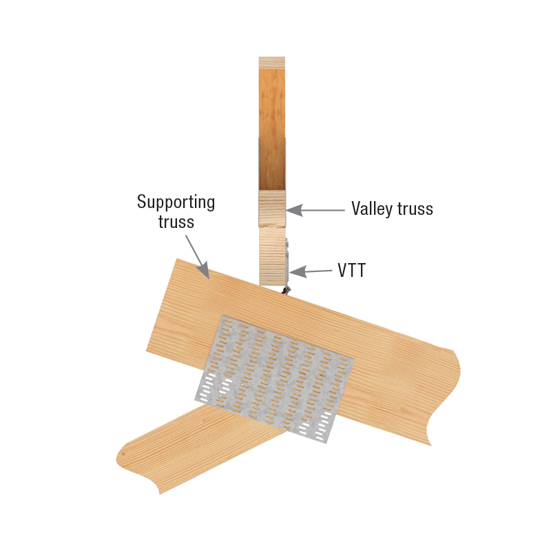
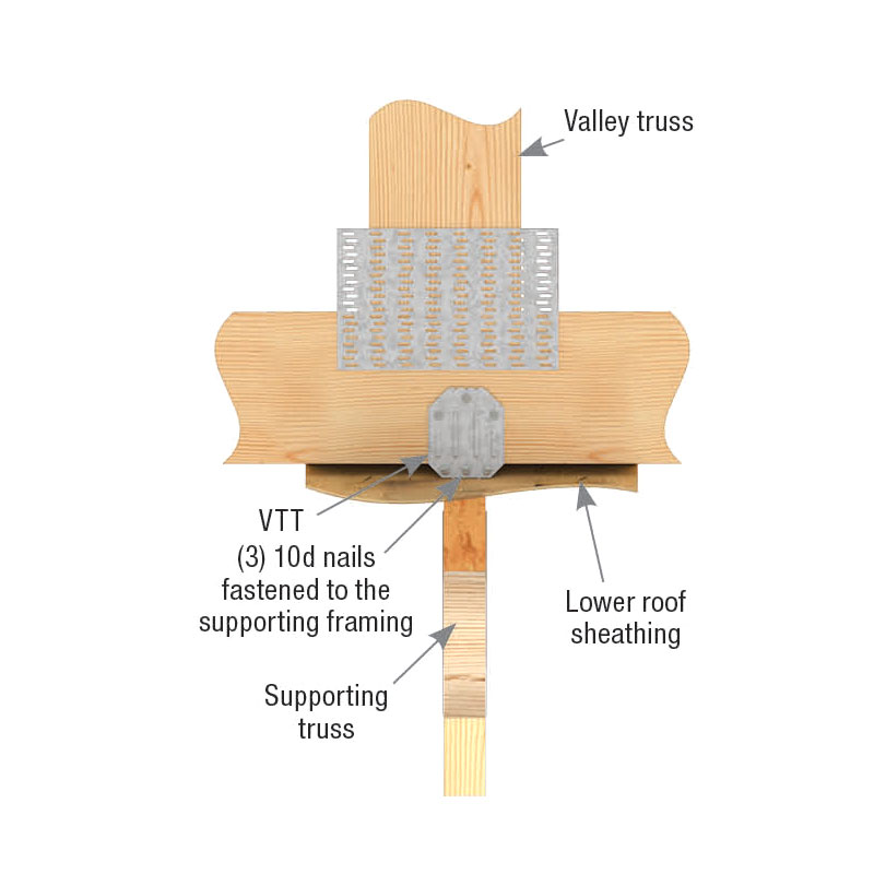
The VTT is a Valley Truss Tie designed to transfer loads from a valley truss into the supporting structure below. It also resists the sliding forces from downward loads when the valley truss is set upon a sloped lower roof. The ability to resist the sliding force eliminates the need for support wedges under the valley truss bottom chord or special order valley roof trusses with a bevel-cut bottom chord.
Patents: U.S. Patent No. 9,920,514 B1
Features:
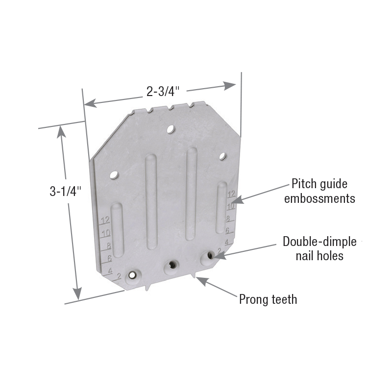
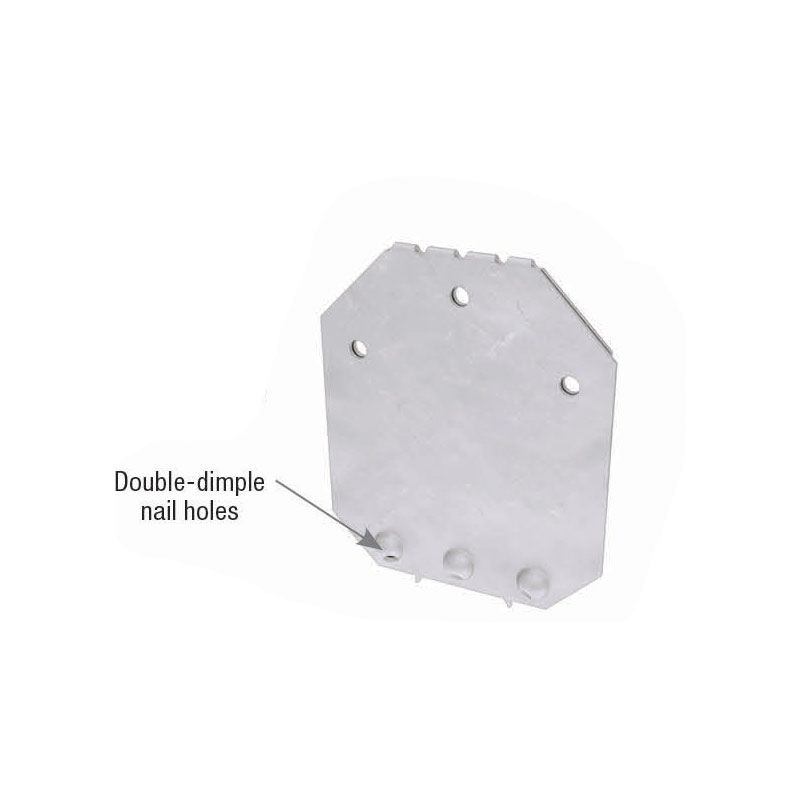
• Double-dimple nail holes assure the nails are driven in at the correct angle into the supporting member every time.
• Flat design requires no field bending to match the supporting roof pitch.
• 2-Ply steel with stiffening ribs provides a high resistance to sliding forces from downward loads.
• Prong teeth help hold the VTT in place while nailing.
• Accommodates supporting roof pitches from 0/12 to 12/12.
• Pitch guide embossments allow attachment to valley truss on ground.
Patents: U.S. Patent No. 9,920,514 B1
Features:
• Double-dimple nail holes assure the nails are driven in at the correct angle into the supporting member every time.
• Flat design requires no field bending to match the supporting roof pitch.
• 2-Ply steel with stiffening ribs provides a high resistance to sliding forces from downward loads.
• Prong teeth help hold the VTT in place while nailing.
• Accommodates supporting roof pitches from 0/12 to 12/12.
• Pitch guide embossments allow attachment to valley truss on ground.
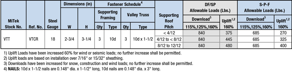
Materials: 18 gauge
Finish: G90 galvanizing
Code Reports:
View Code Report Table
Resources
MiTek Product CatalogInstallation
- Mark the location of the supporting truss located below the lower roof sheathing.
- Place the VTT flat against the valley truss, centered over the top chord of the truss below. Tap the top edge down with a hammer to engage the prong teeth.
- Nail the VTT to the bottom chord of the valley truss using (3) 10d x 1-1/2″ nails.
- I nstall (3) 10d common nails through the double-dimples and drive them through the sheathing into the top chord of the supporting truss below. One nail will be centered in the top chord below. The other two nails are driven in at preset angles guided by the dimple holes.
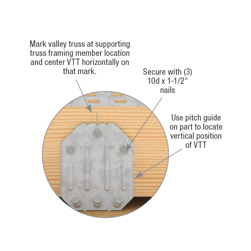
Alternate Installation for Ground/Pre-Placement of VTT - Mark the location of the supporting truss located below the lower roof sheathing. Center VTT horizontally on that mark.
- Use pitch guide embossments on part to locate the vertical position of VTT. Pitch numbers on connector are the numerator in the pitch slope ratio. (i.e. “6” indicates a 6/12 pitch, “12” indicates a 12/12 pitch, etc.)
- Secure the VTT to valley truss with (3) 10d x 1-1/2” nails.
- When valley truss is hoisted into proper position on roof, install (3) 10d common nails through the double-dimples and drive them through the sheathing into the top chord of the supporting truss below. One nail will be centered in the top chord below. The other two nails are driven in at a preset angles guided by the dimple holes.
Need Help or Have a Question? Contact Customer Service or Call 800-328-5934
VTT Front View
Code Report Table
VTT
3-View Product Drawings
| MiTek Stock # | Download or View Files | |||
|---|---|---|---|---|
| VTT | DWG | DXF | View Image | |
Contact us for test data